
As wireless communication networks and the environments in which they are deployed continue to evolve, so too do the methods used in designing them. One major challenge continually facing utilities and vendors is the design of large mesh AMI networks, particularly those being deployed in dense urban markets. The inherently complex nature of these networks, combined with their changing architectures, presents many obstacles in designing a system that meets budget projections and performance requirements. This article will discuss the proper modeling and dimensioning of large-scale mesh AMI networks in complex urban environments as compared to traditional forms of network planning methodology.
When one considers wireless network design, it may call to mind wide-area coverage networks employing a ‘tower site’ type of system to cover a service area. To be sure, this system architecture may even work for some AMI applications being deployed in rural areas or areas with low meter densities. However, when we start planning networks consisting of hundreds of thousands or even millions of nodes in very dense urban areas, this approach quickly becomes impractical. First, a meter that is out of range in this type of network will require added infrastructure to be connected back to the network, thus adding great cost to the deployment. Second, a tower in this type of architecture would quickly become overloaded and the system would not meet its performance requirements. Due to interference considerations and spectrum restraints, it would not be feasible in this scenario to simply add more sites. By lowering the collector antenna height in urban deployments, we are limiting the interference range of each collector while maximizing capacity within limited spectrum resources. However, planning networks in these low-height topologies presents a new set of challenges. Among these is addressing a much more complex propagation environment containing many more potential sites than the aforementioned tower site systems.
One of the most important aspects of planning a mesh network is the building of a 3D model of the environment in which the network will be deployed. This is typically done with terrain and clutter data and often times, clutter height and building data. As devices in these networks are typically mounted on assets 20 to 40 feet above ground level, it becomes obvious that environmental factors such as structures, foliage, roadways and other clutter considerations are going to play a major part in the performance of the system. As such, it is imperative to work with data that will provide an accurate representation of the environment. The examples in this article depict 1m/30m hybrid data from EGS Technologies, which contains data with resolutions as high as one meter. Hybrid data is made up of imagery from different sources to provide the highest resolution possible in the areas where it is most applicable. For example; you would most likely see higher resolution data in dense, urban areas and lower resolution in rural areas that are sparser in land use considerations and do not require a higher resolution database. With the cost of many high resolution databases difficult to justify, particularly when their benefit is limited to dense urban area, a hybrid database then becomes a very attractive option.
Even with high resolution data, situations found in real-world service areas such as limited or non-ideal mounting locations provide for many challenges in network design. One of the few propagation models that has served these type of urban environment predictions, ray-tracing, has historically not been optimal for large network design due to long study processing times. However, there are platforms available today that utilize GPU acceleration to offer ray tracing models that are orders of magnitude faster than traditional models. By utilizing detailed building data and taking into account all features of the environment, ray-tracing solutions offer site specific calculations that are highly accurate and detailed prediction of how signals will interact within complex environments consisting of any number of features and potential obstructions.
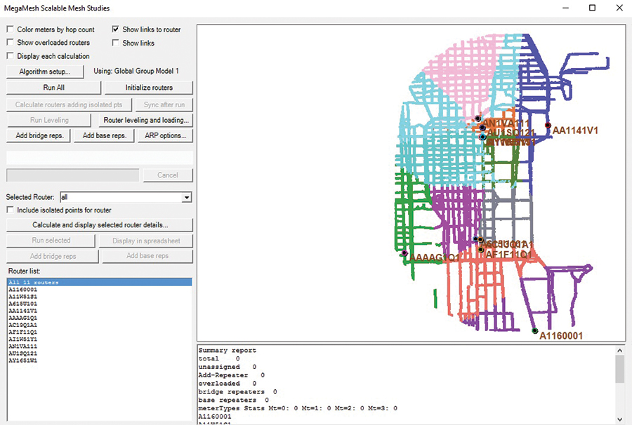
Further complicating matters in the design of these mesh AMI networks are all the potential links that must be considered. Because these mesh architectures consist of millions of possible communication links; with collectors linking to meters and repeaters, repeaters to meters and other repeaters, and meters to every other device etc., we know that it would not be possible to manually check every one of these possible links. Nor would it be feasible or efficient for a planning tool to make all of the possible calculations in a reasonable amount of time unless it has been calibrated to do so. EDX technology with the Mesh Network Module has been designed to not only run all of these calculations efficiently, but also allow for the engineer to impose their vendor specific capacity constraints on the various equipment, providing for further system design capabilities.
By considering these capacity constraints on the front-end of the overall network design, the utility or vendor will have achieved a more efficient and cost effective network design. This is in contrast to what you might see in the ‘tower site network’ application mentioned previously. A network such as this might employ a simple coverage analysis of the various network hierarchy layers. Typically, such a methodology would begin with the planning of the collector sites, located based on an average radius as determined by the largest distance a meter can be away from the collector and still mesh through the other network layers. After the collectors are placed, a coverage analysis would be performed to determine those locations where repeaters need to be added. When problems with these systems arise after deployment, the typical way of fixing them is to add repeaters where needed. This approach leads to system over-provisioning and therefore higher costs. But there are also consequences to the overall function of the network in this type of overprovisioning scenario. The performance of the network will experience degradation through increased mesh hopping and the associated rise of the noise floor as well as an increase in system latency. Furthermore, this type of design methodology will not consider individual equipment capacity aspects which can further contribute to decreased network performance. It will also not identify critical system nodes or take into account the RF performance of each individual link in the network.
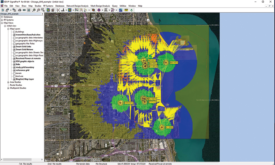
A more effective design approach is to begin by ensuring a robust physical network layer. Because each AMI network will have capacity and hopping limitations, it is critical that the network design be aware and take into account these constraints. This is achieved with a thorough system design, using a tool that performs calculations for each of the potential links in the system. Another feature of this latest tool is that each link calculation considers minimum link power, hopping limits per device type, capacity limits per device type and performs calculations taking into account the 3D environment that has been modeled (terrain, clutter, building data etc) - creating a detailed RF physical layer. This design methodology ensures a robust physical layer and eliminates uncertainties among potential network links.
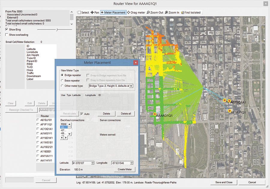
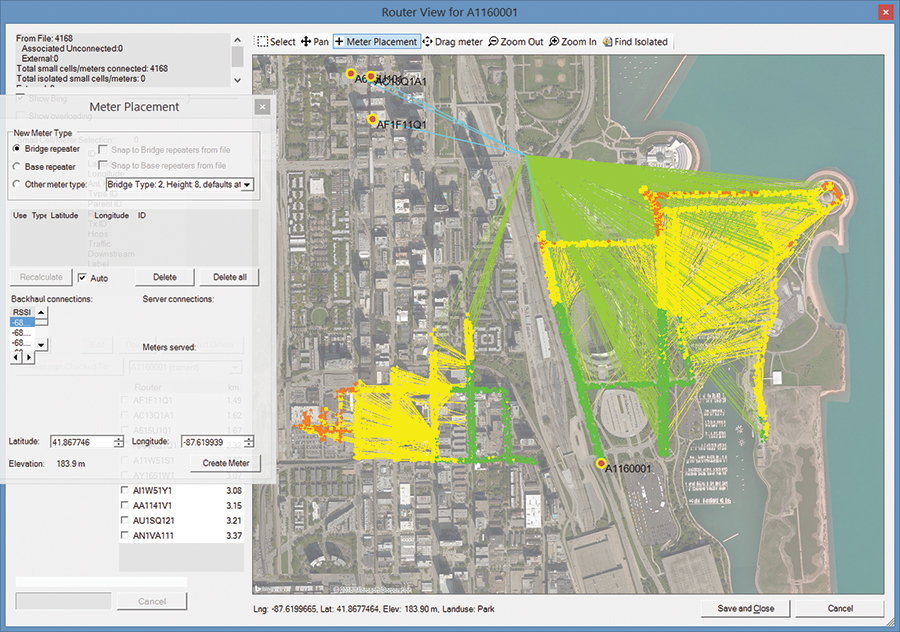
When it comes to repeaters it is essential to select not only the appropriate number of repeaters, but also the appropriate location. A repeater that is not properly located could easily become a main path for many devices, potentially causing a bottleneck in the network architecture and creating a single point of failure. A properly balanced system will feature the appropriate number of repeaters in the ideal location. These potential bottlenecks and single points of failure can be identified through a capacity constrained type study in a mesh link model.
There are several such factors to consider when locating equipment. And when we are dealing with very large networks consisting of a large number of devices, determining these locations is no small task. Fortunately, a fully featured tool contains many automated process that aid in these tasks.
A typical AMI network design begins with the importing of meter locations and potential candidate locations including poles, substations and/or street data. The technology in this latest planning tool distributes collectors based on these imported locations and automatically assigns the minimum number of collectors to cover devices based on receive sensitivity, maximum number of hops per device, and maximum router distance. Similar automated processes are also available for repeaters wherein the program automatically chooses the best repeater location based on potential repeater candidate locations. These locations can either be a predefined list of candidates that are imported into the tool, or an engineer may define a service area and let the program create a list of potential repeater locations. The tool also calculates connectivity in real time based on cursor location. With a map of your service area open in the program, you can move your cursor around the screen and in doing so, will have visualization of all the connections available based on the cursor’s location. These features streamline pre-sales activities as well as the initial and subsequent system design iterations.
The design of AMI networks, along with the service area environments in which they are deployed, are becoming increasingly complex. As they do, it becomes essential to work with a planning tool that will properly plan, dimension and optimize these networks. EDX platform contains the features and automated process to take you through every stage of the network lifecycle.
About the Author
 Bob Akins is the sales and marketing manager at EDX Wireless. He is responsible for identifying and developing new opportunities across the wireless industry and actively contributes to not only sales and marketing, but also support and product development. In this role, Akins has worked with utilities, smart grid vendors and consultants world-wide as they plan and deploy AMI, distribution automation and other mesh networks. Mr. Akins joined EDX in 2012.