Introduction
Gone are the days of the simple electro-mechanical relay without firmware and communication interfaces. The fact exists that protection and control systems have changed significantly in the past decade and will continue to change with technology advancements. The digital world has impacted the protection system from the introduction of microprocessor based relays in the 1980s to protection relays with communication interfaces in the 1990s. Today’s advanced digital protective relays utilize high speed communication to replace copper wires for inter-bay control, safety interlocking and even breaker trip and closing. Modern sensor technology also allows for the digitization and analog acquisition in the switchyard replacing hazardous inductive CT and PT circuits with process bus communications.
The Digital World has brought many benefits but also introduces challenges. This paper will focus on the impact of the protection and control system as a result of microprocessor relay introduction in the 1990s. It will discuss key issues the protection and control engineer has encountered in the past and will face with the deployment of the advanced protective relay. Key areas discussed will be performance and benefits including the digitization and transfer function of Nonconventional Instrument Transformers, security threats and best practices for the protection system, fleet management in the age of NERC PRC/CIP regulations and performance consideration to achieve high availability of the protection and control system. As well the paper will address some protection issues such as; since fiber optic current sensor systems have no iron, and no CT saturation, the differential relay need not have multiple slopes to account for CT performance, just a minimum pick up thus increasing the sensitivity several fold.
The educational benefits to understanding these impacts is paramount in the adoption and embracing of modern monitoring and control systems. Understanding the requirements to improve the performance of the substation automation protection and control systems is the goal to create the informed decision maker embracing these advancements in new technology which from a reliability perspective can greatly improve the overall power system performance.
1. Background
After the introduction of microprocessor based relays in the 1980s, the change to protection relays with communication interfaces in the 1990s had relatively little impact on the protection systems as such, but enabled integration of protection devices into substation automation protection and control systems.
Although the introduction of IEC 61850 standard opened-up opportunities for improved integration of protection and control relays of different vendors into automation systems, it had very little or no impact on the protection functions itself. Only now by extending the application of the same standard to the process level for data exchange between the primary system and the protection and control IEDs (intelligent electronic devices), it starts to play a mission critical role in the power system protection. The Digital Substation solution’s key technologies (relays, advanced substation automation and modern instrument transformers) are the advantages where IEC 61850/ Ethernet are positioned as technology enablers and not obstacles.
2. The Standard – IEC 61850
First multifunction microprocessor relays were developed in the early 1980s. One was based on the Washington State University Master’s Degree Thesis by Ravi Iyer. He joined Brown Boveri Corporation under the mentorship of Stanley Zocholl to design the distribution protection unit becoming the first multifunction microprocessor relay in 1984. This relay performed three phase and ground instantaneous and time overcurrent protection, multi-shot circuit breaker reclosing and integrated per phase metering in a single device that was slightly larger than two single phase electromechanical overcurrent relays. The innovation of the modern digital system roots from this era by the industry pioneers understanding the interworks of the electro-mechanical relationship to engage the revolutionary computer scientist replacing induction discs and spring constants with data acquisition, digital conversion and four point algorithms. These early devices were based on 8-bit microprocessors and programmed in highly optimized assembly source code as the algorithms had to be extremely efficient and program memory size of 64 kilobytes was a luxury.
The microprocessor relay is our industries first venture into The Digital World and it has revolutionized our protection and control systems. The key benefit of the microprocessor relay has been the significant reduction of panel space required to accomplish the same protection system. Figure 1 depicts a line protection system for 1½ breaker arrangement.
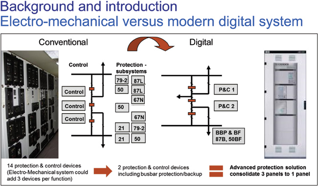
Figure 1: Substations secondary systems showing the same application
with electro-mechanical relays versus modern digital system
(click to enlarge)
In the Figure 1 example, the protection function indicated by the ANSI relay elements were traditionally implemented utilizing discrete relays requiring several relay panels to protect this scheme. The utilization of modern multi-object (protection of more than one primary apparatus) relays and open standards for device to device communications allows for functional consolidation, elimination of control and interlocking copper wire interconnections greatly improving the system performance while increasing both reliability and personnel safety.
The most significant change, good and bad, was the introduction of software systems to perform these system protections. Early implementation had limited software source code as the microprocessor power and memory size limited the amount of functionality permissible. As the multi-functional relay advanced and started communicating to RTU and gateways, the complexity of the device software system also increased. The good is that protection system performance increased tenfold while the bad was the introduction of the undocumented feature also known as software bugs. The firmware version management is now a crucial element of the utility fleet management to ensure that the installed protection devices do not lead to unwanted system performance. For the American Bulk Energy System, the North American Reliability Corporation (NERC) has developed a set of reliability and critical infrastructure protection standards to support overall grid reliability, stability and security.
The protection and control system may seldom be called upon to operate until the abnormal condition threatens the apparatus. It is this instance that the system must operate to protect the utility assets. A major benefit of the modern protection devices is the advanced self-diagnostics and self-supervision to ensure the highest availability of the system. Electro-mechanical and solid state relays were only found to be non-operational when a fault occurred resulting in a misoperation or during routine testing. The modern protection device has advanced diagnostics to ensure performance or indicate of pending problems.
Today, the digital world continues to morph as modern primary apparatus embeds digital technology and the benefits of non-conventional instrument transformers further improve system performance and personnel safety. These enablers on the primary system process level will continue revolutionizing the next generation of system protection, control and automation.
3. The Digital Systems
In the digital system, sampled analog values are communicated according IEC 61850 9 2 from merging units or non-conventional instrument transformers (NCITs) to the protection and control IEDs and trip commands are sent as IEC 61850 GOOSE messages to the circuit breaker interfaces. By this, the communication system becomes a critical part in the fault clearance chain affecting the total fault clearance time of the protection system.
4. From copper wiring to process bus
Approaching the installation of a process bus communication network, which connects the bay level equipment like protection and control IEDs or metering devices to the merging units and breaker IEDs located at process level, is motivated by different aspects:
4.1. Increased safety
Every copper wire in a substation is a potential risk whether it is from a CT or PT circuit or a 125V DC control wire. The highly inductive current transformer secondary circuit poses the largest safety concern. The hazard results when an energized current transformer wire is unknowingly disconnected. From inductive circuit theory, current flowing through an inductive circuit cannot be instantaneously changed from 5 Amps to zero. A quick thanks to Wikipedia; the mathematics v(t) = L formula implicitly states that a voltage is induced across an inductor, equal to the product of the inductor’s inductance, and current’s rate of change through the inductor. As the inductance does not change during the open circuit, the rate of change in current from 5 to 0 Amps instantaneously has the derivative (di/dt) resultant go to infinity. Thus, the formula’s product voltage is dominated by the derivative blowing up to infinity and produces a very large voltage across the open circuited wires. Related to the substation application, an open CT secondary is equivalent to the inductive current going to zero and depending on the secondary load, arcing will occur as these dangerously high voltages build putting field personnel at risk of serious injury or even fatality and equipment and the substation at risk from electrical fire. Minimizing copper leads to greatly improved safety.
4.2. Less material
Using fiber optics instead of copper cables not only reduces the copper cabling in a substation by around 80 percent, depending on voltage level and switchgear type and layout. It also means less material transport to site.
If conventional instrument transformers are replaces by non-conventional ones, further weight can be saved. An optical CT for a 400kV AIS installation weights about 20% of its conventional (SF6 filled) counterpart.
4.3. Shorter installation time and shorter outage time for secondary system retrofits
Less cables to be pulled, less equipment to be connected and less connections to be tested. This leads on one hand to shorter installation times of new secondary systems, on the other hand it also helps to reduces outage times during secondary system replacements. The outage time in the latter case can be reduces due to the shorter time required to install the new equipment, but also because the new equipment comes from the factory fully tested from SCADA through protection and control IEDs to process interfaces. Hence testing of the new system that requires outages is reduced.
5. Fault clearance times of digital substations
When approaching to use NCITs and Ethernet communication to transfer mission critical analog and binary data for protection functions, the tripping speed does not depend anymore only on the protection IED and tripping relays. In digital systems, the fault clearance time is depending on the performance of all involved electronic components like NCITs, merging units, protection IEDs and breaker IEDs, as well as on the design of the process bus communication system.
The expectation on the digital system is that they fulfill today’s specifications and regulations regarding fault clearance time and that they perform at least as good as today’s protection systems. A typical figure for fault clearance times under normal conditions (without failures in protection system or circuit breaker) is four power cycles. Two cycles are considered for the circuit breaker opening with extinguishing of the arc and two cycles are assumed for the protection system. These figures can be found in international standard like IEC 60834 [3] and national regulations like NERC’s technical paper on protection system reliability [6] or National Grid UK’s grid code [5].
Two of the times in the above figure are defined and categorized by international standards. The ‘processing delay time’ of NCITs and merging units is defined in IEC 60044-8 [12] as rated delay time, which shall not exceed 3ms for protection applications. The ‘Transfer time’ definition is part of IEC 61850-5 [9]. For both, sampled values and trip commands sent via GOOSE, the highest transfer time performance class applies, which shall be 3ms or less. The transfer time is the sum of the times required by the stack of the sending device, the stack of the receiving device and the communication system. According to IEC 61850 10 [10] and IEC 61850 90 4 [14], the 3ms are assumed to be split 80 percent to the processing times in the IED stacks (2.4ms) and the remaining 20 percent (0.6ms) for the communication network.
Table 1 Overview of the standard or typical timings in the fault clearance chain, as well as the timings that are achievable with modern devices and appropriate communication system design. The IED logic processing time, ie the time required by the protection algorithm is assumed to be one 60Hz power cycle in both cases.
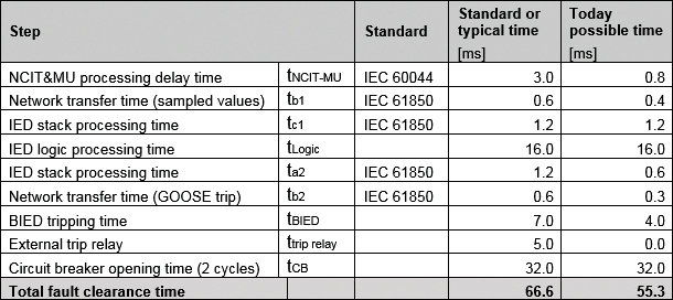
Table 1: Time budget with standard respectively typical times and possible times with modern devices.
One important point in the second column with the today possible times, is that the external trip relay is omitted and the circuit breaker is directly tripped by the breaker IEDs power outputs. But even if the trip relay is in place, the total fault clearance time requirement of 4 power cycles, as mentioned above, can be undercut significantly.
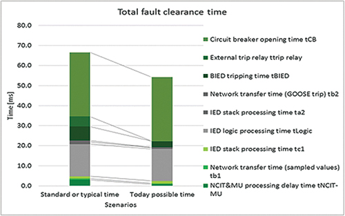
Figure 2: Time budget with standard respectively typical times and possible times with modern devices
More details on the above used calculation scheme, as well as more in depth explanations and analysis can be found in [2].
6. Impacts of non-conventional instrument transformers
That non-conventional instrument transformers can provide excellent accuracy of 0.2 percent or better has been demonstrated in various installations, where the NCITs have been connected to IEC 61850-9-2 process bus enabled grid meters. To verify the accuracy of the digital measuring chain, they have been installed in parallel to a conventional metering system. The installation described in [8], showed that after three years of operation the difference of the accumulated energy measured by the conventional and the digital system was at around 0.35 percent. This is not the absolute accuracy but the difference of the two measuring systems, which could be up to 0.8 percent as both systems were allowed to introduce errors of 0.2 percent for current and voltage.
Even better results are presented in [7], which describes two installations with NCITs, process bus and grid meters. Here the observed differences for active energy between conventional and non-conventional systems range from 0.01 to 0.19 percent, far lower than the tolerable error given the accuracy classes of the installed conventional instrument transformers and NCITs of class 0.2 and 0.2s respectively.
6.2. Transient performance
Transient performance classes of instrument transformers play important roles in dimensioning protection applications. The protection performance and transient performance is defined in IEC 60044 and IEC 61869. Instrument transformers standard IEC 61869 is replacing the old IEC 60044 standard. The parts for conventional instrument transformers are already released, but for non-conventional or electronic CTs and VTs, still the old standard has to be used. In both cases they describe the behavior at the secondary interface of the instrument transformers, which are the terminal blocks in case of conventional CTs and VTs and the communication interface in case of their non-conventional variants.
Along with the definitions of IEC 61850 9 2 and also the “Implementation Guideline for Digital Interface to Instrument Transformers using IEC 61850-9-2” [13], commonly known as IEC 61850 9 2LE, the instrument transformer standards hence allow to sufficiently describe NCITs and enable building multivendor installations.
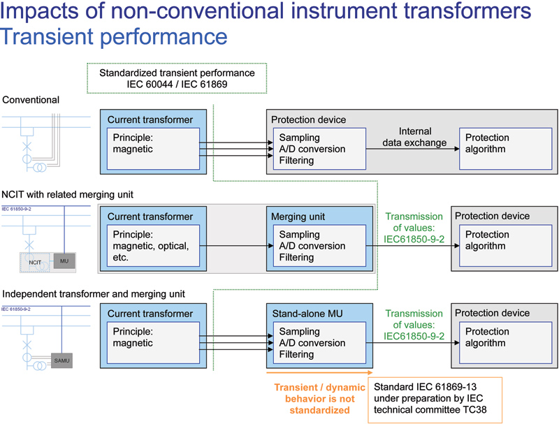
Figure 3: Interfaces and standardization
(click to enlarge)
Until the IEC 61869 standard part is ready, interoperability beyond communication of the stand-alone merging unit of one vendor with the protection relay of another vendor has to be carefully verified. Complete system testing stressing the dynamic performance and transient response of the analog conversion is critical to ensure proper system operation.
6.3. Optimized placing of measuring points in the substation
Thanks to its compact nature, the placement of non-conventional current and/or voltage transformers in the switchyard can be optimized to improve overlapping of protection zones. Figure gives an example of a simplified 1½. breaker arrangement with NCITs installed at each side of the circuit breakers. In this setup the protection zones of busbar and line protection as well as the protected zones by the line protection overlap. In case of air-insulated systems, the NCITs can be integrated in the bushings of the circuit breaker or in case of gas-insulated systems; they can be located at each side of the circuit breaker between breaker and disconnectors.
In case of combined NCITs for current and voltage, more voltage measuring points than normal are available in a diameter, which results in biggest flexibility in choosing voltage sources for e.g., synchrocheck and distance protection functions.
6.4. Benefit of sensors not saturating
The result of using a current sensor that does not saturate can have a profound effect on the setting, and thus the sensitivity of a relay. Take for example, the differential relay. A differential relay relies on current sensors to provide the exact reproduction of the primary currents to it for analysis. It then adds the current vectors together and computes a differential current. Then using an operating curve, as shown in Figure 8 determines whether to operate or not. If the differential current falls above the characteristic curve for a given restraint current, the relay operates. If not, it restrains.
The slopes in red section, and green section are there to adjust for the performance of a conventional current transformer. As the restraint current goes up, the chances of two conventional current transformer operating exactly the same reduces. This output difference between the current transformers is compensated for by increasing the slope of the characteristic such that more differential current is needed to operate as the restraint current increases. The red section typically has a slope of 40%, and the green section typically has a slope of 80%. While this compensation is necessary for conventional current transformers to make it secure during current transformer saturation, it has the effect of decreasing the sensitivity of the differential scheme. With the use of non-conventional current sensors, these slopes can be set to close to zero which increases the sensitivity of the differential scheme during high current conditions.
Part II of the article along with all references will appear in the Nov/Dec issue.
About the Authors
 Stefan Meier has been working with ABB Switzerland for more than 15 years. He held several positions, from commissioning of substation automation systems, through technical support and project management. Today he is a global product manager for process bus solutions, where he coordinates the introduction IEC 61850 process bus in pilot and commercial projects. Stefan studied electrical science at the University of Applied Sciences Northwestern Switzerland, and holds a master degree in business administration from Edinburgh Business School of Heriot-Watt University, Scotland.
 Steve Kunsman is a recognized Substation Automation Specialist with over 32 years in substation automation, protection and control applications, communications technologies (IEC 61850 and DNP), cyber security for substation automation, and the Relion product family of protection and control relays. His ABB career began in 1984 as an Electrical Designer for the protective relay group and has held various engineering, technology and product management positions within the North American and global substation automation organizations. Steve holds a B.S. in Electrical Engineering from the Lafayette College in Easton, Pennsylvania and an MBA in management of technology from Lehigh University in Bethlehem, Pennsylvania.