
Use of the arc reflection method combined with a high capacitance surge generator and state-of-the-art pinpointing devices for underground cable fault locating will find faults in less time and with less risk of damaging good cable than classical techniques.
Time Domain Reflectometry
The pulse reflection method, pulse echo method or time domain reflectometry are several terms applied to what is referred to as cable radar or a TDR. The technique, developed in the late 1940's, makes it possible to connect to one end of a cable, actually see into the cable and measure distance to changes in the cable. The original acronym Radar (Radio Detection And Ranging) was applied to the method of detecting distant aircraft and determining their range and velocity by analyzing reflections of radio waves. This technique is used by airport radar systems and police radar guns where a portion of the transmitted radio waves are reflected from an aircraft or ground vehicle back to a receiving antenna. For cable radar, when applied to underground cable, short time duration pulses are transmitted at a high repetition rate into the cable between the phase conductor and shield (neutral). A liquid crystal or CRT display shows reflections of the transmitted pulses. Reflections are caused by changes in the characteristic impedance of the cable. Any reflections are displayed on the screen with elapsed time along the horizontal axis and amplitude of the reflection on the vertical axis. Since we can now measure elapsed time and if we know the pulse velocity as it travels down the cable, distance to the reflection point can be calculated. For airport radar and police radar guns the velocity of propagation (Vp) of the radio waves through air is very nearly the speed of light or 984 ft/ms. Pulses transmitted through the insulation of our underground cable travel at about half that or about 500 ft/µs. A good cable analysis system should include two movable cursors which, when positioned at zero and a reflection point, provide a measurement of distance to that point, in feet.
A TDR sees each increment of cable, say each foot, as the equivalent electrical circuit shown in Figure 1. The combination of these components is referred to as the characteristic impedance (Z0) of the cable. If every increment of cable is perfect and exactly the same, all components of the equivalent circuit of every foot are also exactly the same. This perfect run of cable will produce no reflections until the end of the cable appears. At the end of the cable the pulses see a high impedance, an open circuit, causing an upward (+100%) reflection. See Figure 2.
If the cable end is grounded, a short circuit, the pulses see a low resistance and a downward (-100%) reflection is caused. See Figure 3.
A low voltage TDR is an excellent tool for the prelocation of open circuits and conductor-toconductor shorts. For shielded power cables, faults with a resistance higher than 200 ohms are almost impossible to distinguish from normal clutter reflections on the cable. Unfortunately almost all faults on primary underground distribution cable are high resistance faults in the area of thousands of ohms or even megohms. Due to the reflection characteristics of these high resistance faults they are impossible to see using only the low voltage TDR.
Arc Reflection Method
The arc reflection method of fault prelocating combines the use of a TDR (cable radar) and a surge generator (thumper). By using an arc reflection filter, a low voltage TDR and a high voltage surge generator can both be connected to the faulted cable and the TDR can be looking down the cable while thumping. The filter protects the TDR from the surge generator high voltage pulses and routes the low voltage pulses down the cable. This method utilizes the fact that when an arc is created at the fault, its resistance is reduced to a very low value, less than 200 ohms, which will reflect radar pulses. The arc location will appear as a downward going reflection on the TDR cable trace. See Figure 4. The cable analysis systems should capture and store the complete trace including the downward going fault location in memory so measurements can be made easily. Rather than thumping and walking the cable route to discover the fault location, the cable analysis system should provide a prelocation measurement with as little as one or two thumps and about 95% of the time gets you within 10 to 20 feet of the fault. Pinpointing efforts can then be concentrated within a welldefined section of the cable. This technique substantially reduces the amount of high voltage exposure to the cable, preventing the initiation of new faults, which will surface after the cable is put back into service.
Surge Generator
The device is basically a high voltage pulse generator consisting of a dc power supply, a high voltage capacitor and some type of high voltage switch. The power supply is used to charge the capacitor to a high voltage and then a contact closure discharges the capacitor into the cable under test. If the voltage is high enough to break down the fault, the energy stored in the capacitor is rapidly discharged through an arc at the fault creating a detectable sound or “thump” at ground level. The important specifications of a thumper are how high a voltage can be developed and how much energy is delivered to the fault. The energy output of any surge generator measured in Joules (Watt-Seconds) is calculated as follows:
The classical fault locating process is to hook up the surge generator, crank up the voltage and walk the cable route until the thump is heard or better yet felt. This process pinpoints the fault allowing a repair crew to dig a hole and repair the cable. The higher the voltage, the bigger the bang and the easier it is to find the fault. In some cases it takes hours (or days) to locate the fault and all that time the cable is being exposed to high voltage thumping. A few years after polyethylene cable began to be installed underground, evidence began to surface that due to “treeing” in the insulation, high voltage thumping of this plastic cable was doing more harm than good. Due to this information many utilities have issued work rules reducing the voltage to be used for fault locating. Another fact of life is that from the point of discharge at the fault to the isolated end, the cable sees a peak-topeak voltage wave of double the surge voltage at every thump.
A very common surge generator in use for many years included a 4 microfarad capacitor that generated 1250 Joules at a voltage of 25 kV. If the fault locating crew is told that the maximum output voltage of the thumper must be limited to 12.5 kV (one half of 25 kV), the output energy of their thumper is reduced by a factor of four down to 312 Joules. In a practical world, the threshold for hearing a thump at ground level with no acoustic amplification and no background noise is in the range of 300 to 400 Joules. If the thump at the fault cannot be heard, voltage will have to be increased in order to find the fault, make a repair and get the lights back on.
Ideally, a surge generator that uses a 12 microfarad capacitor, which allows thumping at lower voltages while still delivering reasonable energy to the fault, is required. Thumping at 12.5 kV, as above, now produces a very audible 937 Joules. The surge generator, when thumping at its maximum voltage of 16 kV, produces 1536 Joules and should include both a built-in arc reflection filter and surge pulse pickup.
Pinpointing
Before digging in order to repair the faulted cable, some type of pinpointing technique must be used. The classical methods all revolve around some means to enable hearing the sound produced by the discharge of energy at the fault. The simplest and well-used method is the fault-locatorear- on-the-ground-butt-in-the-air technique. Other approaches involve traffic cones, shovel handles and a length of conduit. Slightly more modern equipment uses electronic amplification and an acoustic pickup positioned on the ground. These techniques all assume that the sound travels directly from the fault to the earth’s surface unimpeded and that the loudest sound is directly above the fault. If the cable is in duct or conduit or under paving this assumption may not be valid. A surge detector/fault pinpointer that combines an electromagnetic surge pickup and one or two acoustic pickups to zero in on the fault is the instrument of choice here. The receiver measures and displays the elapsed time between surge and sound. As the fault is approached, this time interval decreases to a minimum directly over the fault. This technique relies on the timing between the two events, not just simply on the volume of the sound. If dual acoustic pickups are used, the receiver will also indicate which direction to move toward the fault.
Conclusion
Using the combination of a cable analysis system, a surge generator and a surge detector/fault pinpointer, the process of underground fault locating becomes more efficient, gets service restored quicker and minimizes the possibility of programming the cable for additional faults while finding the present fault.
Time Domain Reflectometry
The pulse reflection method, pulse echo method or time domain reflectometry are several terms applied to what is referred to as cable radar or a TDR. The technique, developed in the late 1940's, makes it possible to connect to one end of a cable, actually see into the cable and measure distance to changes in the cable. The original acronym Radar (Radio Detection And Ranging) was applied to the method of detecting distant aircraft and determining their range and velocity by analyzing reflections of radio waves. This technique is used by airport radar systems and police radar guns where a portion of the transmitted radio waves are reflected from an aircraft or ground vehicle back to a receiving antenna. For cable radar, when applied to underground cable, short time duration pulses are transmitted at a high repetition rate into the cable between the phase conductor and shield (neutral). A liquid crystal or CRT display shows reflections of the transmitted pulses. Reflections are caused by changes in the characteristic impedance of the cable. Any reflections are displayed on the screen with elapsed time along the horizontal axis and amplitude of the reflection on the vertical axis. Since we can now measure elapsed time and if we know the pulse velocity as it travels down the cable, distance to the reflection point can be calculated. For airport radar and police radar guns the velocity of propagation (Vp) of the radio waves through air is very nearly the speed of light or 984 ft/ms. Pulses transmitted through the insulation of our underground cable travel at about half that or about 500 ft/µs. A good cable analysis system should include two movable cursors which, when positioned at zero and a reflection point, provide a measurement of distance to that point, in feet.
A TDR sees each increment of cable, say each foot, as the equivalent electrical circuit shown in Figure 1. The combination of these components is referred to as the characteristic impedance (Z0) of the cable. If every increment of cable is perfect and exactly the same, all components of the equivalent circuit of every foot are also exactly the same. This perfect run of cable will produce no reflections until the end of the cable appears. At the end of the cable the pulses see a high impedance, an open circuit, causing an upward (+100%) reflection. See Figure 2.
If the cable end is grounded, a short circuit, the pulses see a low resistance and a downward (-100%) reflection is caused. See Figure 3.
A low voltage TDR is an excellent tool for the prelocation of open circuits and conductor-toconductor shorts. For shielded power cables, faults with a resistance higher than 200 ohms are almost impossible to distinguish from normal clutter reflections on the cable. Unfortunately almost all faults on primary underground distribution cable are high resistance faults in the area of thousands of ohms or even megohms. Due to the reflection characteristics of these high resistance faults they are impossible to see using only the low voltage TDR.
Arc Reflection Method
The arc reflection method of fault prelocating combines the use of a TDR (cable radar) and a surge generator (thumper). By using an arc reflection filter, a low voltage TDR and a high voltage surge generator can both be connected to the faulted cable and the TDR can be looking down the cable while thumping. The filter protects the TDR from the surge generator high voltage pulses and routes the low voltage pulses down the cable. This method utilizes the fact that when an arc is created at the fault, its resistance is reduced to a very low value, less than 200 ohms, which will reflect radar pulses. The arc location will appear as a downward going reflection on the TDR cable trace. See Figure 4. The cable analysis systems should capture and store the complete trace including the downward going fault location in memory so measurements can be made easily. Rather than thumping and walking the cable route to discover the fault location, the cable analysis system should provide a prelocation measurement with as little as one or two thumps and about 95% of the time gets you within 10 to 20 feet of the fault. Pinpointing efforts can then be concentrated within a welldefined section of the cable. This technique substantially reduces the amount of high voltage exposure to the cable, preventing the initiation of new faults, which will surface after the cable is put back into service.
Surge Generator
The device is basically a high voltage pulse generator consisting of a dc power supply, a high voltage capacitor and some type of high voltage switch. The power supply is used to charge the capacitor to a high voltage and then a contact closure discharges the capacitor into the cable under test. If the voltage is high enough to break down the fault, the energy stored in the capacitor is rapidly discharged through an arc at the fault creating a detectable sound or “thump” at ground level. The important specifications of a thumper are how high a voltage can be developed and how much energy is delivered to the fault. The energy output of any surge generator measured in Joules (Watt-Seconds) is calculated as follows:

E = Energy in Joules, C = capacitor in mf, V = voltage in kV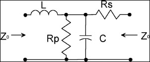
Figure 1. Cable Incremental Equivalent Circuit
The classical fault locating process is to hook up the surge generator, crank up the voltage and walk the cable route until the thump is heard or better yet felt. This process pinpoints the fault allowing a repair crew to dig a hole and repair the cable. The higher the voltage, the bigger the bang and the easier it is to find the fault. In some cases it takes hours (or days) to locate the fault and all that time the cable is being exposed to high voltage thumping. A few years after polyethylene cable began to be installed underground, evidence began to surface that due to “treeing” in the insulation, high voltage thumping of this plastic cable was doing more harm than good. Due to this information many utilities have issued work rules reducing the voltage to be used for fault locating. Another fact of life is that from the point of discharge at the fault to the isolated end, the cable sees a peak-topeak voltage wave of double the surge voltage at every thump.
A very common surge generator in use for many years included a 4 microfarad capacitor that generated 1250 Joules at a voltage of 25 kV. If the fault locating crew is told that the maximum output voltage of the thumper must be limited to 12.5 kV (one half of 25 kV), the output energy of their thumper is reduced by a factor of four down to 312 Joules. In a practical world, the threshold for hearing a thump at ground level with no acoustic amplification and no background noise is in the range of 300 to 400 Joules. If the thump at the fault cannot be heard, voltage will have to be increased in order to find the fault, make a repair and get the lights back on.
Ideally, a surge generator that uses a 12 microfarad capacitor, which allows thumping at lower voltages while still delivering reasonable energy to the fault, is required. Thumping at 12.5 kV, as above, now produces a very audible 937 Joules. The surge generator, when thumping at its maximum voltage of 16 kV, produces 1536 Joules and should include both a built-in arc reflection filter and surge pulse pickup.
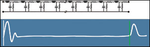
Figure 2. Equivalent Circuit and Low-Voltage TDR Trace with Open End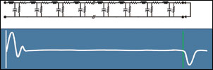
Figure 3. Equivalent Circuit and Low-Voltage TDR Trace with Grounded End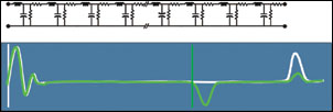
Figure 4. Equivalent Circuit, TDR Traces showing Fault Location
Pinpointing
Before digging in order to repair the faulted cable, some type of pinpointing technique must be used. The classical methods all revolve around some means to enable hearing the sound produced by the discharge of energy at the fault. The simplest and well-used method is the fault-locatorear- on-the-ground-butt-in-the-air technique. Other approaches involve traffic cones, shovel handles and a length of conduit. Slightly more modern equipment uses electronic amplification and an acoustic pickup positioned on the ground. These techniques all assume that the sound travels directly from the fault to the earth’s surface unimpeded and that the loudest sound is directly above the fault. If the cable is in duct or conduit or under paving this assumption may not be valid. A surge detector/fault pinpointer that combines an electromagnetic surge pickup and one or two acoustic pickups to zero in on the fault is the instrument of choice here. The receiver measures and displays the elapsed time between surge and sound. As the fault is approached, this time interval decreases to a minimum directly over the fault. This technique relies on the timing between the two events, not just simply on the volume of the sound. If dual acoustic pickups are used, the receiver will also indicate which direction to move toward the fault.
Conclusion
Using the combination of a cable analysis system, a surge generator and a surge detector/fault pinpointer, the process of underground fault locating becomes more efficient, gets service restored quicker and minimizes the possibility of programming the cable for additional faults while finding the present fault.