
Combined with the powerful graphical user interface (GUI) EMTPWorks, EMTP-RV—the new restructured version of the well-known electromagnetic transient program EMTP—sets a higher level of capabilities in the simulation of large-scale electrical networks. It’s now possible to rapidly design, simulate and view large and complex systems, reducing the engineering and development time and allowing more detailed studies on the complex phenomena of power system transients.
Powerful engine
EMTP-RV uses a completely new approach for assembling network equations: sparse modified-augmented-nodal analysis. A new Jacobian-based nonlinear solver eliminates all topological restrictions and allows solving very large-scale nonlinear systems with a minimized number of iterations. All EMTP-RV network models can be combined and solved in any topological configuration without forcing the user to introduce artificial devices to circumvent numerical problems.
In addition to a large library of electrical/electronic circuit and power system devices, EMTP-RV can solve control systems using block diagrams. A library of primitive devices is used to build libraries of specialized control functions. EMTP-RV has a completely new control system solver and an optional Newton method for finding the simultaneous solution of all control system blocks.
Power electronics circuits can be solved using macro-models, such as ideal switches and detailed nonlinear functions. Simultaneous switching is achieved by treating the switches in an iterative loop.
In addition to its time-domain solution, EMTP-RV has a complex matrix-based steady-state solution used primarily in automatic initialization of state-variables. Automatic initialization is for achieving quick harmonic steady-state in the first time-domain simulation cycle. All devices, including the distributed parameter transmission line models and machines with controllers, can be initialized.
The new EMTP-RV code has been rewritten from scratch using modern object-oriented programming and vectorized computations. In addition to flexibility for user-defined modeling, one of the most important benefits to the user is its significantly increased speed of computation and fully automatic dynamic memory management. There are no built-in limits for the number of devices or signals in any topological configurations and device combinations. EMTP-RV is optimized for speed and memory.
EMTP-RV minimizes numerical limitations and topological restrictions for providing an environment of unsurpassed expressive power for the user. Although complex and powerful, it remains straightforward to harness for conducting studies at all user levels.
Intuitive and user-friendly GUI
EMTPWorks is also the simulation environment for EMTP-RV. It’s designed to efficiently create and maintain small circuits as well as very large-scale networks. EMTPWorks has an open architecture for maximized user configurability from basic user-defined model assemblies to more advanced script-based programming. EMTPWorks offers script methods from simple data management tasks to more advanced object attribute settings, library functions and network device symbol redrawing and updating. Each device is given its data web using DHTML. Device data Web pages can reside on the user’s computer or anywhere on the Web. The script source code of all device data management functions is available to the user. EMTP-RV has automatic subcircuit creation methods with unlimited levels of hierarchy. Subcircuit masking options can accommodate user programming from simple data statements to more complex scripts and data capture panels. Scripts can be also used to launch calls to ActiveX objects or to programs created in other environments.
Multipage design
A circuit can be drawn on one or more pages (up to 1000 in this version). You can elect to draw the entire circuit on a single page or divide it up functionally onto a number of pages.
Each page is viewed in a separate circuit window, and any or all pages in a circuit can be displayed on the screen simultaneously.
A page is drawn on the screen as if it was a single piece of paper, although it may have to be broken up into a number of individual sheets of paper for printing or plotting.
Logical connections can be made between pages using a page connector device.
Due to the the software’s ability to connect signals by name, signals with the same name appearing on different pages are automatically connected. The inter-page connections are used to place a visual marker and provide a mechanism for jumping between pages through connected signals.
The entire Hydro-Quebec grid was modeled using this approach. This is a very large network divided into several regions and subcircuits having over 16,000 devices.
Hierarchical design and subcircuits
“Hierarchy” refers to the ability to have a “device” symbol in a schematic actually represent an arbitrary circuit block. The “pins” on the device symbol represent connections to specific input-output points on the internal circuit. Subcircuits (also called subnetworks) are the building blocks of hierarchy.
Hierarchical design provides a powerful way of representing complex designs in a compact and readable form. A top-level diagram of your system can show only major functional blocks. These blocks can then be opened to show more and more design details.
Hierarchical design in effect adds a “third dimension” to a schematic diagram. It also raises some complex issues that should be understood before embarking on a major design.
After creating the subcircuit, the user can mask its data using scripts. Masking is a powerful feature for data hiding and encapsulation. It is part of the open-architecture options in EMTP-EMTPWorks. It provides high-level access to subcircuit contents and allows the creation and programming of a user-defined model.
User-defined symbols and device libraries
Devices with their symbols and data are an important resource in your design creation process. Whether you primarily use the devices provided with EMTPWorks, or you create special libraries for your own use, the completeness and accuracy of device maintenance tools has a major effect on your design flow. Library files generally outlast any one design and are used for many years across many projects. In addition, many EMTPWorks features rely on specific steps being taken while creating a symbol. For these reasons, EMTPWorks provides a variety of features for creating and editing the device symbols and for maintaining device library files.
Symbols are created and edited using the device Symbol Editor tool. In addition to drawing symbols, the device symbol editor is also used for fixing device behavioral attributes in the schematic. One of the most useful applications of the Symbol Editor is the customization of subcircuit symbols. When a subcircuit is created the first time, EMTPWorks uses a default rectangular symbol. You can right-click on the symbol and select “Edit Symbol” to open the Symbol Editor window and modify the device drawing.
Using the symbol editor, you can customize the device drawing to give a realistic representation. This helps to provide a more comprehensible view of the network.
Efficient output processors
The EMTP-RV package includes an efficient data acquisition and processing software named ScopeView. It is especially well adapted for the simultaneous viewing and mathematical post-processing of EMTP-RV, but can also show MATLAB® and COMTRADE generated signals. ScopeView offers multi-page and multi-column capabilities and an advanced built-in function editor.
EMTP-RV provides another visualization function called MPLOT, suited for waveform viewing and statistical analysis. MPLOT is entirely written using MATLAB®, and is the compiled version of a set of m-files. It’s also available as a free download for users who want to used MPLOT directly from MATLAB® for increased flexibility and access to a very large set of data manipulation and calculation functions.
Practical applications
With the new computational and visual environment provided by EMTP-RV, users can now handle a much larger time-scale in their studies. The new speed of computation allows them to study lightning phenomena as well as transient stability problems. It is now possible to simulate much more complex and advanced designs with increased precision. The EMTP-RV software package provides several examples demonstrating its capabilities in various application fields. The list of examples includes:
Additional examples and user contributions are continuously added and made available for EMTP-RV users through the EMTP-RV website (www.emtp.com).
A client oriented product
EMTP-RV is commercialized by TransÉnergie Technologies and is maintained by a research and development team and experienced EMTP users. In addition to providing world-class support and maintenance services, TransÉnergie Technologies offers superior consulting and training options.
A one-week seminar and computer workshops on different aspects of transient system studies and analysis with EMTP-RV is held twice yearly. Short seminars are also organized as part of the major Power System conferences and trade shows. Scheduled EMTP-RV training courses and seminars will be announced in advance on the EMTP-RV website (www.emtp.com).
For more information: khodabakhchian.bahram@hydro.qc.ca
EMTP-RV is developed and maintained by the Development Coordination Group of EMTP which includes American Electric Power, CEA Technologies, CRIEPI of Japan, Electric Power Research Institute, Électricité de France, Hydro One Networks, Hydro-Québec, US Bureau of Reclamation and Western Area Power Administration.
Powerful engine
EMTP-RV uses a completely new approach for assembling network equations: sparse modified-augmented-nodal analysis. A new Jacobian-based nonlinear solver eliminates all topological restrictions and allows solving very large-scale nonlinear systems with a minimized number of iterations. All EMTP-RV network models can be combined and solved in any topological configuration without forcing the user to introduce artificial devices to circumvent numerical problems.
In addition to a large library of electrical/electronic circuit and power system devices, EMTP-RV can solve control systems using block diagrams. A library of primitive devices is used to build libraries of specialized control functions. EMTP-RV has a completely new control system solver and an optional Newton method for finding the simultaneous solution of all control system blocks.
Power electronics circuits can be solved using macro-models, such as ideal switches and detailed nonlinear functions. Simultaneous switching is achieved by treating the switches in an iterative loop.
In addition to its time-domain solution, EMTP-RV has a complex matrix-based steady-state solution used primarily in automatic initialization of state-variables. Automatic initialization is for achieving quick harmonic steady-state in the first time-domain simulation cycle. All devices, including the distributed parameter transmission line models and machines with controllers, can be initialized.
The new EMTP-RV code has been rewritten from scratch using modern object-oriented programming and vectorized computations. In addition to flexibility for user-defined modeling, one of the most important benefits to the user is its significantly increased speed of computation and fully automatic dynamic memory management. There are no built-in limits for the number of devices or signals in any topological configurations and device combinations. EMTP-RV is optimized for speed and memory.
EMTP-RV minimizes numerical limitations and topological restrictions for providing an environment of unsurpassed expressive power for the user. Although complex and powerful, it remains straightforward to harness for conducting studies at all user levels.
Intuitive and user-friendly GUI
EMTPWorks is also the simulation environment for EMTP-RV. It’s designed to efficiently create and maintain small circuits as well as very large-scale networks. EMTPWorks has an open architecture for maximized user configurability from basic user-defined model assemblies to more advanced script-based programming. EMTPWorks offers script methods from simple data management tasks to more advanced object attribute settings, library functions and network device symbol redrawing and updating. Each device is given its data web using DHTML. Device data Web pages can reside on the user’s computer or anywhere on the Web. The script source code of all device data management functions is available to the user. EMTP-RV has automatic subcircuit creation methods with unlimited levels of hierarchy. Subcircuit masking options can accommodate user programming from simple data statements to more complex scripts and data capture panels. Scripts can be also used to launch calls to ActiveX objects or to programs created in other environments.
Multipage design
A circuit can be drawn on one or more pages (up to 1000 in this version). You can elect to draw the entire circuit on a single page or divide it up functionally onto a number of pages.
Each page is viewed in a separate circuit window, and any or all pages in a circuit can be displayed on the screen simultaneously.
A page is drawn on the screen as if it was a single piece of paper, although it may have to be broken up into a number of individual sheets of paper for printing or plotting.
Logical connections can be made between pages using a page connector device.
Due to the the software’s ability to connect signals by name, signals with the same name appearing on different pages are automatically connected. The inter-page connections are used to place a visual marker and provide a mechanism for jumping between pages through connected signals.
The entire Hydro-Quebec grid was modeled using this approach. This is a very large network divided into several regions and subcircuits having over 16,000 devices.
Hierarchical design and subcircuits
“Hierarchy” refers to the ability to have a “device” symbol in a schematic actually represent an arbitrary circuit block. The “pins” on the device symbol represent connections to specific input-output points on the internal circuit. Subcircuits (also called subnetworks) are the building blocks of hierarchy.
Hierarchical design provides a powerful way of representing complex designs in a compact and readable form. A top-level diagram of your system can show only major functional blocks. These blocks can then be opened to show more and more design details.
Hierarchical design in effect adds a “third dimension” to a schematic diagram. It also raises some complex issues that should be understood before embarking on a major design.
After creating the subcircuit, the user can mask its data using scripts. Masking is a powerful feature for data hiding and encapsulation. It is part of the open-architecture options in EMTP-EMTPWorks. It provides high-level access to subcircuit contents and allows the creation and programming of a user-defined model.
User-defined symbols and device libraries
Devices with their symbols and data are an important resource in your design creation process. Whether you primarily use the devices provided with EMTPWorks, or you create special libraries for your own use, the completeness and accuracy of device maintenance tools has a major effect on your design flow. Library files generally outlast any one design and are used for many years across many projects. In addition, many EMTPWorks features rely on specific steps being taken while creating a symbol. For these reasons, EMTPWorks provides a variety of features for creating and editing the device symbols and for maintaining device library files.
Symbols are created and edited using the device Symbol Editor tool. In addition to drawing symbols, the device symbol editor is also used for fixing device behavioral attributes in the schematic. One of the most useful applications of the Symbol Editor is the customization of subcircuit symbols. When a subcircuit is created the first time, EMTPWorks uses a default rectangular symbol. You can right-click on the symbol and select “Edit Symbol” to open the Symbol Editor window and modify the device drawing.
Using the symbol editor, you can customize the device drawing to give a realistic representation. This helps to provide a more comprehensible view of the network.
Efficient output processors
The EMTP-RV package includes an efficient data acquisition and processing software named ScopeView. It is especially well adapted for the simultaneous viewing and mathematical post-processing of EMTP-RV, but can also show MATLAB® and COMTRADE generated signals. ScopeView offers multi-page and multi-column capabilities and an advanced built-in function editor.
EMTP-RV provides another visualization function called MPLOT, suited for waveform viewing and statistical analysis. MPLOT is entirely written using MATLAB®, and is the compiled version of a set of m-files. It’s also available as a free download for users who want to used MPLOT directly from MATLAB® for increased flexibility and access to a very large set of data manipulation and calculation functions.
Practical applications
With the new computational and visual environment provided by EMTP-RV, users can now handle a much larger time-scale in their studies. The new speed of computation allows them to study lightning phenomena as well as transient stability problems. It is now possible to simulate much more complex and advanced designs with increased precision. The EMTP-RV software package provides several examples demonstrating its capabilities in various application fields. The list of examples includes:
- Lightning strike near a 765-kV GIS. To assess the wide spectrum of the propagated signals, the transmission lines are modeled using frequency-dependent models. The towers near the substation are modeled in detail using a transmission line model to represent the tower height and a dynamic model for the footing resistance. The GIS substation is also modeled in detail using transmission lines for the busbars and the gas-filled bushing.
- 765-kV line crossing a river with the special use of line arresters. This example simulates the protection provided by the line arresters against the very fast rising current injected by lightning.
- Variable static load modeling and machine dynamics. Here the loads are divided into several types representing real-life consumption: incandescent light, fluorescent light, small motor, large motor and TV load.
- Single-phase induction machine. EMTP-RV is the first simulation program to represent this type of machine in detail. This flexible model provides several initialization modes, with or without capacitor run and with or without the secondary winding.
- Arc instability following shunt reactor breaker failure. The modeling of the arc breaker in this design was able to identify a new transient phenomenon and helped to solve an actual substation breaker failures.
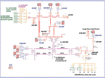
- Distributed generation with wind power and multi-machine transient stability of a large network. This rather large and complex network includes 10 synchronous machines, 4 distributed wind power generators, a dynamic load model, power electronics, STATCOM, etc. This design shows the power of EMTP-RV modeling using multilevel subcircuits with masks to enter the data. symbol editor is used to add clarity and to give a comprehensive view of the entire network.
Additional examples and user contributions are continuously added and made available for EMTP-RV users through the EMTP-RV website (www.emtp.com).
A client oriented product
EMTP-RV is commercialized by TransÉnergie Technologies and is maintained by a research and development team and experienced EMTP users. In addition to providing world-class support and maintenance services, TransÉnergie Technologies offers superior consulting and training options.
A one-week seminar and computer workshops on different aspects of transient system studies and analysis with EMTP-RV is held twice yearly. Short seminars are also organized as part of the major Power System conferences and trade shows. Scheduled EMTP-RV training courses and seminars will be announced in advance on the EMTP-RV website (www.emtp.com).
For more information: khodabakhchian.bahram@hydro.qc.ca
EMTP-RV is developed and maintained by the Development Coordination Group of EMTP which includes American Electric Power, CEA Technologies, CRIEPI of Japan, Electric Power Research Institute, Électricité de France, Hydro One Networks, Hydro-Québec, US Bureau of Reclamation and Western Area Power Administration.