
Preface
Electrical power transmission networks are protected and controlled by medium and high-voltage circuit breakers.
Breakers are meant to make and break the flow of electrical currents in transmission lines. Being so, the electrical contact function plays a main and critical role in the breaker's proper operation.
In the present article you will find a summarized description of the different types of electrical contacts used in power circuit breakers, the major risks to their proper operation and the principal tests used to verify their condition.
INTRODUCTION
A circuit breaker is an automatically operated electrical switch designed to protect an electrical circuit from damage caused by an overload or a short circuit. Unlike a fuse, which operates once and then has to be replaced, a circuit breaker can be reset (either manually or automatically) to resume normal operation.
Circuit breakers are made in varying sizes, from small devices, which protect an individual household appliance, up to large switchgear designed to protect high voltage circuits feeding an entire city.
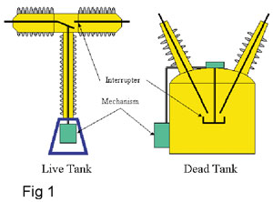
The high voltage circuit breaker has three major components:
Interrupting Chamber: where the current conduction and interruption in the power circuit occurs. It is usually a closed volume containing the make-break contacts and an interrupting medium (compressed air, oil, SF6, vacuum, etc.) used for insulation and arc quenching.
Operating Mechanism: where the needed energy to close or to open the contacts and to quench the arc is initiated.
Control: where the orders to operate the breaker are generated and its status is monitored.
Electrical contacts in Circuit breakers
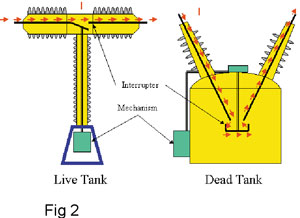
As mentioned earlier, the power current passes through the conducting material in the interrupting chamber (fig 2). Various parts that are joined together form the conducting material. The different junctions form the electrical contacts.
Electrical contact is obtained by placing two conducting objects in physical contact. This can be done in several ways. Even though there is a wide range of contact designs in interrupting chambers, they may be grouped in four major categories:
Figure 3 is a symbolic schematic of a typical contact architecture and clearly shows the current flow through three of the main types of contacts during the sequence of events of an open operation. In all three types, the contact is made by the touching surfaces of each component.
Make-Break Contacts
The types of make-break contacts can be subdivided by power rating, starting with the highest:
High current, high voltage circuit breaker contacts, which disconnect large electrical loads, and produce arcs, are contained within special arcing chambers. These may be in air at normal pressure or in a blast of air, in Sulfur Hexafluoride (SF6), in oil or another arc-extinguishing medium, including a vacuum.
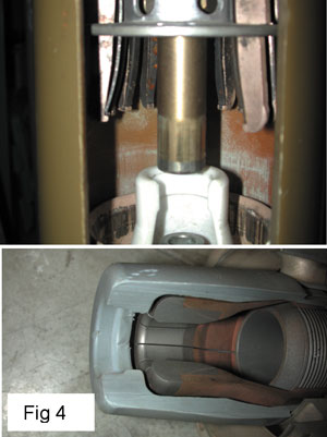
It includes a moving contact and a stationary contact. Usually one of them is a ring of sprung copper contact fingers (insertion type, fig 4 or butt type), or the other is a solid rod of copper. The contacts may be tipped with an arc-resistant material to resist erosion from the high-power arc, and the surfaces may be plated (e.g. with silver) to improve conductivity.
The mechanical properties of copper combined with its excellent electrical conductivity and good arcing endurance in oil have made it the preferred metal in this application.
In vacuum circuit breakers, the contacts are also generally copper, mixed with tungsten and specially shaped to ensure proper distribution of the electric field and movement of the arc root.
Smaller air break circuit breakers (medium voltage), use copper in all internal conducting parts, but the contacts are often faced with a silver based alloy to resist welding. Such circuit breakers, being protective devices, rarely open or close.
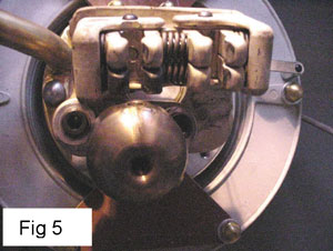
Sliding Contacts (Fig.5)
These can be of very different nature.
High speed, heavy current types, they are usually found in power interrupter Chambers. These contacts must have a very high resistance to mechanical wear, as their relative speed may reach 10 meters per second or more.
Fixed Contacts
These include a wide range of bolted and crimped contacts.
A clamped joint avoids the reduction in cross section caused by drilling to insert bolts, and gives a more uniform distribution of the contact force, making the contact more efficient and hence running cooler. Bolting is used because it is cheap and convenient.
Crimped joints employ the ultimate extreme force of contact making, causing the metal to flow and make a permanent connection. The trouble-free nature of these joints, and the simplicity and rapidity of the crimping operation makes this type of joint very attractive for permanent connections.
Bolted or crimped contacts are used in interrupting chambers to secure and to maintain the integrity of the electrical component.
Demountable Contacts
Found in medium voltage metal clad breakers. It helps in taking the breaker off the network by easily sliding it off the bus bars for maintenance purposes. This has to be done off load.
These contacts, like the make-break contacts, may be carrying high currents at high voltages (e.g. high voltage isolators or high or medium voltage fuse contacts). They have to carry current reliably for long periods, without overheating or loss of contact, but do not make or break current. They are not subjected to the stress of arcing; hence they do not get the inherent cleaning action associated with it. They are frequently designed to have some frictional action on closing to remove superficial oxide or corrosion films which might impede contact, and copper and its alloys are the most frequently used materials for the bulk of demountable contacts.
The characteristic of these contacts is that they have a high contact force, much higher than for circuit breakers of similar current rating, but not so high as the contact force in a bolted contact, because of the excessive mechanical wear which would be caused when separating the contacts
Contact Resistance
As we said, the contact occurs when two surfaces touch. For the electric current, if it is conductive material, it means a path for it to flow.
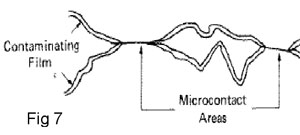
Observation on a microscopic scale shows that the contact surface is actually rough even though it seems smooth to the unaided eye.
In fact, as the microscope shows, the real contact between two surfaces happens through a number of small surfaces, called microcontacts (fig 7), spread randomly inside the limits of the visible contact area.
It is the sum of the areas of all the microcontacts that constitutes the effective contact area.
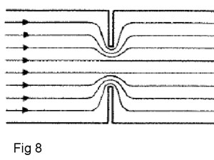
Since the resistance of an electrical contact is inversely proportional to the contact area, the smaller the effective area the greater the resistance. (fig 8)
Effect of Contact Resistance
When a current I pass through an area A that has a resistance R, The Energy E absorbed by A is:
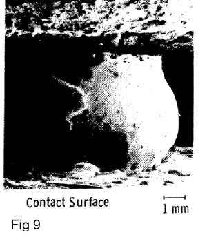
For a constant current Io, if R increases, E then increases, leading to increasing temperature of the contact. If T continues to increase the material of the contact can reach its melting point, leading to its destruction. (fig 9)
Elements affecting the contact resistance
Oxidation
A thin layer of insulating oxide covering the area of a single microcontact would have little effect on the conductivity of the contact as a whole. As soon as the oxide layer extends to a significant number of microcontacts, the current-bearing area would reduce, thus increasing its resistance. Increased resistance will increase the contact temperature, leading to its destruction.
All ambient atmospheres that contains gases capable to react with the contact's material, such as O2, SO2, H2O, H2S, etc., would be favorable to producing oxide layers even though the contact is closed. With time, the gas would succeed in penetrating and reacting with the contact surface to degrade its characteristics and to increase its resistance.
WILLIAMSON studied the phenomenon. Fig 10 shows the resistance value increasing with time. As we can see, the resistance change is not significant until a certain point in time where the degradation increases fast. Similar results are obtained by LEMELSON for copper contacts in oil.
These results show interesting behavior and indicate the urgency of a maintenance intervention when a contact's resistance starts to increase.
Contact wear
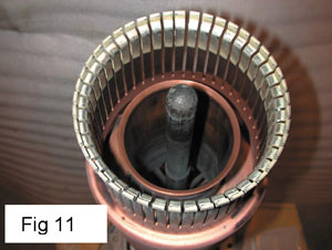
Mechanically, it can be due to the movement and friction of the contacts and electrically due to the arc effect (mainly the make-break contact). Contact wear directly affects the contact resistance and makes it increase dramatically if the wear is in an advanced state (fig 11).
Fretting
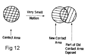
A form of accelerated oxidation is possible, if the contact surfaces experience a cycling movement relatively to each other. For example, the contacts would not close at the same area each time.
This phenomenon was noticed long ago but its magnitude was recognized only recently. When a contact moves from its previous position, a part is exposed to the ambient atmosphere. An oxidation layer then forms. When the contact goes back to this position, it breaks the thin layer and pushes it aside. This phenomenon repeats many times until the oxidation layer becomes of a significant thickness, enough to increase its resistance.
BRAUNOVIC has experimented the fretting phenomena with low currents in aluminum, and JOHNSON & MOBERLY have studied it on high currents and reached similar results.
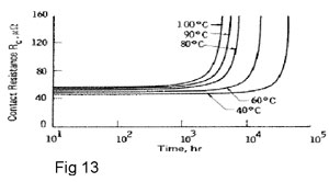
The resistance increases rapidly right after it starts to change. Fig 13 shows similar case to fig 10, but accelerated.
Contact Force
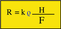
As known, the resistance R is function of the contact material’s resistivity p and area S, (R= p / S).
S is the sum of all contact points areas.
The contact points areas are function of the applied force F and the material hardness H,
(k is a constant)
If F decreases, S decreases as well and R then increases.
F can decrease due to different factors, for example:
Spring materials are thus an important element to take into consideration. By the same logic, an important precaution to take is to avoid letting the spring be a current path, as the increase in its temperature would cause a weakness of the resultant force F.
Temperature
For an increasing temperature T of the contacts, the material of the contacts may soften to the point where it will reduce the contact force, leading to a quick increase of the contact resistance.
Testing
We have seen above that oxidation, wear, fretting, force and temperature directly affect the resistance value R (in microohms) of the contacts.
So, to easily assess the conditions of the breaker contacts, two types of tests, to both statically and dynamically measure R, have established themselves and are widely in use.
Contact Resistance Measuring
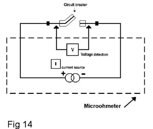
Measuring the contact resistance is usually done by using the principles of Ohm’s law V = RI;
V is the voltage across the contact;
I is the current;
R is the resistance.
If we apply a current I and we measure the voltage V, the resistance R can be obtained directly by dividing V by I.
R= V/I
As seen in fig 14
Since the interrupting chamber is a closed container, we have only access to the entry and exit conductors; the measured R between these two points would be the sum of all the contact resistances found in series, (fixed, make-break and sliding contacts).
According to the IEC 694, article 6.4.1, the current value to use should be the closest to the nominal current the interrupting chamber is designed for. If it is impossible to do so lower currents can be used but not less than 50A to eliminate the galvanic effect that might affect the readings.
Special precautions should be observed when measuring:
The unit used is micro ohm ( ).
).
1 = 10-6 ohms ( )
)
We can keep in mind that the range of microohm resistance values found in breakers is roughly divided according to the voltage and
current carrying capacity:
Dynamic Measurement of Contact Resistance
The micro-ohmmeter described above is used to measure the contact resistance with the interrupting chamber in the closed position, but it does not give any indication of the condition of the arcing contacts.
One option is to do an internal inspection but it is time-consuming. In the case of SF6 breakers, maintenance procedures must be strictly followed in order to safely handle the SF6 gas and arc by-products. It is why dynamic contact resistance measurement has been developed.
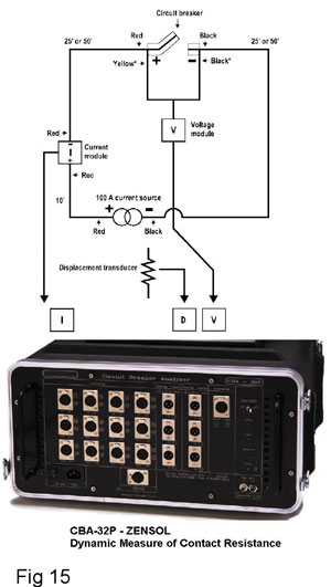
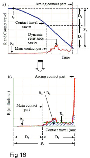
By definition, as its name suggests, starting from a closed position, as the contact moves to its open position, a current is injected and the voltage is measured. This will give us the resistance value all the way from the closed to the open position.
This test needs special equipment (fig 15) and a more complicated procedure compared to the static one. The information collected is of a different nature and give us more insight of the contact's condition that could not be available with the static test.
It is not relevant to discuss the dynamic test in detail in this article. But we can bear in mind that this test is able to give us good information on the resistance value of the arcing contact and the eroded part of it.
This information is crucial for certain breakers, where the quality of arc quenching is greatly affected by this fact. The effect would be so great that it might lead to the explosion of the interrupting chamber.
We also have to know that performing a dynamic contact resistance measurement on butt contacts makes no sense. A simple static test with a micro-ohmmeter is sufficient due to the architecture of the contacts.
So before using the dynamic contact resistance test, you need to check the types and the mechanical architecture of your breaker. This subject will be discussed in more details in our next article.
Summary
The electrical contact is a crucial component in power circuit breakers. An increase in the contact resistance can cause the failure of the breaker.We have seen that all the elements affecting the contact resistance will reach the same result. If the contact resistance starts to increase significantly the increase in value will grow exponentially.
The IEC 56 international standard sets an acceptable reading of up to 20% increase from the original test value. Over this value, it is necessary to perform an open inspection.
It is important to take special precautions while testing since false readings can cause frequent and unnecessary maintenance.
Bibliography
The present article is based on our personal experience.
About the Authors
Emile Nasrallah is an electrical engineer specialized in Power circuit breakers maintenance. Since graduation in 1984 he worked as a field engineer. In1990 he joined the worldwide circuit breaker manufacturer GEC ALSTHOM as a specialized field engineer.In 1997 he became the manager of MV & HV circuit breaker SF6 division of ALSTOM, responsible of technical support, maintenance and training for SF6 circuit breakers. In 2001 he became manager of Air blast circuit breaker division for AREVA. He was in charge of the Air blast (PK and PKV) refurbishing program in partnership with hydro-Quebec and introduced a unique administration system for the program (average of 35, 735 kV PK air blast circuit breaker per year). In 2005 he joined General Electric Company of Canada as a senior circuit breaker specialist and is in charge of the circuit breaker division of the Montreal service centre, responsible of the remanufacturing program for Oil circuit breakers
Stéphan Perron, Hydro-Québec teacher, High Voltage breaker maintenance Stéphan Perron has been teaching maintenance and trouble shooting of High Voltage Circuit Breakers and Thermography for more than 7 years at the Hydro-Quebec Competence Center based in Saint Antoine des Laurentides, QC, Canada. He developped his expertise by working on the maintenance side of the High Voltage Circuit Breakers of Hydro-Quebec for 18 years. His specialties are the ABB (models SFE, HPL, ELF and DLF) breakers, the GE (models KSO, AT) breakers and all the related test instruments, as well as the sectionnors Joslyn VBM, the handling and behavior of the SF6 gaz and interpretation of thermagraphic readings (Level 1) on breakers. Stéphan Perron holds a DEC degree in Electronics from the CEGEP St Jérome, QC, Canada
Dr. Fouad Brikci is the president of Zensol Automation Inc. He was the first to introduce the concept of truly-computerized test equipment in the field of circuit breaker analyzers. As a former university teacher in Ecole Polytechnique — Algiers and CNRS - LAAS researcher in France, Dr. Brikci has developed experience in the fields of electronics, automation, and computer science. Most activities were focused on the industrial application of computers. Among his achievements are the development of fully comput¬erized measuring systems for quality control in circuit breaker manufacturing, laboratories, and maintenance services of electric utilities. Dr. Brikci holds a PhD in Electronics and a Master in Sci¬ences in EEA (electronics, electrotechnics, and automation) from the University of Bordeaux, France. http://www.zensol.com, email : zensol@zensol.com Fouad Brikci, Zensol Automation Inc.
Electrical power transmission networks are protected and controlled by medium and high-voltage circuit breakers.
Breakers are meant to make and break the flow of electrical currents in transmission lines. Being so, the electrical contact function plays a main and critical role in the breaker's proper operation.
In the present article you will find a summarized description of the different types of electrical contacts used in power circuit breakers, the major risks to their proper operation and the principal tests used to verify their condition.
INTRODUCTION
A circuit breaker is an automatically operated electrical switch designed to protect an electrical circuit from damage caused by an overload or a short circuit. Unlike a fuse, which operates once and then has to be replaced, a circuit breaker can be reset (either manually or automatically) to resume normal operation.
Circuit breakers are made in varying sizes, from small devices, which protect an individual household appliance, up to large switchgear designed to protect high voltage circuits feeding an entire city.
The high voltage circuit breaker has three major components:
Interrupting Chamber: where the current conduction and interruption in the power circuit occurs. It is usually a closed volume containing the make-break contacts and an interrupting medium (compressed air, oil, SF6, vacuum, etc.) used for insulation and arc quenching.
Operating Mechanism: where the needed energy to close or to open the contacts and to quench the arc is initiated.
Control: where the orders to operate the breaker are generated and its status is monitored.
Electrical contacts in Circuit breakers
As mentioned earlier, the power current passes through the conducting material in the interrupting chamber (fig 2). Various parts that are joined together form the conducting material. The different junctions form the electrical contacts.
Electrical contact is obtained by placing two conducting objects in physical contact. This can be done in several ways. Even though there is a wide range of contact designs in interrupting chambers, they may be grouped in four major categories:
- Make-break contacts - which may make or break under load;
- Sliding contacts - which maintain contact during relative movement
- Fixed contacts - which may be clamped together permanently for years and never opened.
- Demountable contacts - which make or break off load. Usually seen in metal-clad medium voltage switchgear.
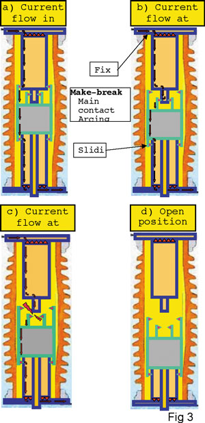
Figure 3 is a symbolic schematic of a typical contact architecture and clearly shows the current flow through three of the main types of contacts during the sequence of events of an open operation. In all three types, the contact is made by the touching surfaces of each component.
Make-Break Contacts
The types of make-break contacts can be subdivided by power rating, starting with the highest:
High current, high voltage circuit breaker contacts, which disconnect large electrical loads, and produce arcs, are contained within special arcing chambers. These may be in air at normal pressure or in a blast of air, in Sulfur Hexafluoride (SF6), in oil or another arc-extinguishing medium, including a vacuum.
It includes a moving contact and a stationary contact. Usually one of them is a ring of sprung copper contact fingers (insertion type, fig 4 or butt type), or the other is a solid rod of copper. The contacts may be tipped with an arc-resistant material to resist erosion from the high-power arc, and the surfaces may be plated (e.g. with silver) to improve conductivity.
The mechanical properties of copper combined with its excellent electrical conductivity and good arcing endurance in oil have made it the preferred metal in this application.
In vacuum circuit breakers, the contacts are also generally copper, mixed with tungsten and specially shaped to ensure proper distribution of the electric field and movement of the arc root.
Smaller air break circuit breakers (medium voltage), use copper in all internal conducting parts, but the contacts are often faced with a silver based alloy to resist welding. Such circuit breakers, being protective devices, rarely open or close.
Sliding Contacts (Fig.5)
These can be of very different nature.
High speed, heavy current types, they are usually found in power interrupter Chambers. These contacts must have a very high resistance to mechanical wear, as their relative speed may reach 10 meters per second or more.
Fixed Contacts
These include a wide range of bolted and crimped contacts.
A clamped joint avoids the reduction in cross section caused by drilling to insert bolts, and gives a more uniform distribution of the contact force, making the contact more efficient and hence running cooler. Bolting is used because it is cheap and convenient.
Crimped joints employ the ultimate extreme force of contact making, causing the metal to flow and make a permanent connection. The trouble-free nature of these joints, and the simplicity and rapidity of the crimping operation makes this type of joint very attractive for permanent connections.
Bolted or crimped contacts are used in interrupting chambers to secure and to maintain the integrity of the electrical component.
Demountable Contacts
Found in medium voltage metal clad breakers. It helps in taking the breaker off the network by easily sliding it off the bus bars for maintenance purposes. This has to be done off load.
These contacts, like the make-break contacts, may be carrying high currents at high voltages (e.g. high voltage isolators or high or medium voltage fuse contacts). They have to carry current reliably for long periods, without overheating or loss of contact, but do not make or break current. They are not subjected to the stress of arcing; hence they do not get the inherent cleaning action associated with it. They are frequently designed to have some frictional action on closing to remove superficial oxide or corrosion films which might impede contact, and copper and its alloys are the most frequently used materials for the bulk of demountable contacts.
The characteristic of these contacts is that they have a high contact force, much higher than for circuit breakers of similar current rating, but not so high as the contact force in a bolted contact, because of the excessive mechanical wear which would be caused when separating the contacts
Contact Resistance
As we said, the contact occurs when two surfaces touch. For the electric current, if it is conductive material, it means a path for it to flow.
Observation on a microscopic scale shows that the contact surface is actually rough even though it seems smooth to the unaided eye.
In fact, as the microscope shows, the real contact between two surfaces happens through a number of small surfaces, called microcontacts (fig 7), spread randomly inside the limits of the visible contact area.
It is the sum of the areas of all the microcontacts that constitutes the effective contact area.
Since the resistance of an electrical contact is inversely proportional to the contact area, the smaller the effective area the greater the resistance. (fig 8)
Effect of Contact Resistance
When a current I pass through an area A that has a resistance R, The Energy E absorbed by A is:
E= RI2t
Where t is the time duration of I.
We know that A’s temperature T is directly related to E by the following equation:
E =  T is a function of the heat dissipation rate.
For a constant current Io, if R increases, E then increases, leading to increasing temperature of the contact. If T continues to increase the material of the contact can reach its melting point, leading to its destruction. (fig 9)
Elements affecting the contact resistance
Oxidation
A thin layer of insulating oxide covering the area of a single microcontact would have little effect on the conductivity of the contact as a whole. As soon as the oxide layer extends to a significant number of microcontacts, the current-bearing area would reduce, thus increasing its resistance. Increased resistance will increase the contact temperature, leading to its destruction.
All ambient atmospheres that contains gases capable to react with the contact's material, such as O2, SO2, H2O, H2S, etc., would be favorable to producing oxide layers even though the contact is closed. With time, the gas would succeed in penetrating and reacting with the contact surface to degrade its characteristics and to increase its resistance.
WILLIAMSON studied the phenomenon. Fig 10 shows the resistance value increasing with time. As we can see, the resistance change is not significant until a certain point in time where the degradation increases fast. Similar results are obtained by LEMELSON for copper contacts in oil.
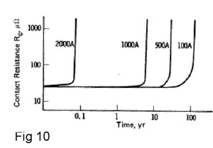
These results show interesting behavior and indicate the urgency of a maintenance intervention when a contact's resistance starts to increase.
Contact wear
Mechanically, it can be due to the movement and friction of the contacts and electrically due to the arc effect (mainly the make-break contact). Contact wear directly affects the contact resistance and makes it increase dramatically if the wear is in an advanced state (fig 11).
Fretting
A form of accelerated oxidation is possible, if the contact surfaces experience a cycling movement relatively to each other. For example, the contacts would not close at the same area each time.
This phenomenon was noticed long ago but its magnitude was recognized only recently. When a contact moves from its previous position, a part is exposed to the ambient atmosphere. An oxidation layer then forms. When the contact goes back to this position, it breaks the thin layer and pushes it aside. This phenomenon repeats many times until the oxidation layer becomes of a significant thickness, enough to increase its resistance.
BRAUNOVIC has experimented the fretting phenomena with low currents in aluminum, and JOHNSON & MOBERLY have studied it on high currents and reached similar results.
The resistance increases rapidly right after it starts to change. Fig 13 shows similar case to fig 10, but accelerated.
Contact Force
As known, the resistance R is function of the contact material’s resistivity p and area S, (R= p / S).
S is the sum of all contact points areas.
The contact points areas are function of the applied force F and the material hardness H,
(k is a constant)
If F decreases, S decreases as well and R then increases.
F can decrease due to different factors, for example:
- Excessive wear of contact surface;
- Fatigue of contact springs over time;
- Chemical reaction of spring material with ambient atmosphere;
- Loose or misaligned contact, etc.
Spring materials are thus an important element to take into consideration. By the same logic, an important precaution to take is to avoid letting the spring be a current path, as the increase in its temperature would cause a weakness of the resultant force F.
Temperature
For an increasing temperature T of the contacts, the material of the contacts may soften to the point where it will reduce the contact force, leading to a quick increase of the contact resistance.
Testing
We have seen above that oxidation, wear, fretting, force and temperature directly affect the resistance value R (in microohms) of the contacts.
So, to easily assess the conditions of the breaker contacts, two types of tests, to both statically and dynamically measure R, have established themselves and are widely in use.
Contact Resistance Measuring
Measuring the contact resistance is usually done by using the principles of Ohm’s law V = RI;
V is the voltage across the contact;
I is the current;
R is the resistance.
If we apply a current I and we measure the voltage V, the resistance R can be obtained directly by dividing V by I.
R= V/I
As seen in fig 14
Since the interrupting chamber is a closed container, we have only access to the entry and exit conductors; the measured R between these two points would be the sum of all the contact resistances found in series, (fixed, make-break and sliding contacts).
According to the IEC 694, article 6.4.1, the current value to use should be the closest to the nominal current the interrupting chamber is designed for. If it is impossible to do so lower currents can be used but not less than 50A to eliminate the galvanic effect that might affect the readings.
Special precautions should be observed when measuring:
- The measured points have to be clean and free of oxidation;
- The measurement points should always be the same each time;
- Perform several consecutive tests and calculate the average.
The unit used is micro ohm (
).1
= 10-6 ohms ()We can keep in mind that the range of microohm resistance values found in breakers is roughly divided according to the voltage and
current carrying capacity:
- 25 kV – 100 to 350 ;
- 120 kV – 80 to 200 ;
- 120 to 330 kV – 100 maximum.
- 735 kV – 20 to 80 .
Dynamic Measurement of Contact Resistance
The micro-ohmmeter described above is used to measure the contact resistance with the interrupting chamber in the closed position, but it does not give any indication of the condition of the arcing contacts.
One option is to do an internal inspection but it is time-consuming. In the case of SF6 breakers, maintenance procedures must be strictly followed in order to safely handle the SF6 gas and arc by-products. It is why dynamic contact resistance measurement has been developed.
By definition, as its name suggests, starting from a closed position, as the contact moves to its open position, a current is injected and the voltage is measured. This will give us the resistance value all the way from the closed to the open position.
This test needs special equipment (fig 15) and a more complicated procedure compared to the static one. The information collected is of a different nature and give us more insight of the contact's condition that could not be available with the static test.
It is not relevant to discuss the dynamic test in detail in this article. But we can bear in mind that this test is able to give us good information on the resistance value of the arcing contact and the eroded part of it.
This information is crucial for certain breakers, where the quality of arc quenching is greatly affected by this fact. The effect would be so great that it might lead to the explosion of the interrupting chamber.
We also have to know that performing a dynamic contact resistance measurement on butt contacts makes no sense. A simple static test with a micro-ohmmeter is sufficient due to the architecture of the contacts.
So before using the dynamic contact resistance test, you need to check the types and the mechanical architecture of your breaker. This subject will be discussed in more details in our next article.
Summary
The electrical contact is a crucial component in power circuit breakers. An increase in the contact resistance can cause the failure of the breaker.We have seen that all the elements affecting the contact resistance will reach the same result. If the contact resistance starts to increase significantly the increase in value will grow exponentially.
The IEC 56 international standard sets an acceptable reading of up to 20% increase from the original test value. Over this value, it is necessary to perform an open inspection.
It is important to take special precautions while testing since false readings can cause frequent and unnecessary maintenance.
Bibliography
The present article is based on our personal experience.
- Power circuit breaker theory and design, edited by C.H. Flurscheim, revised edition 1982;
- Circuit Interruption theory and techniques, edited by Thomas E. Browne Jr., edition 1984;
- J.B.P. Williamson, Deterioration processes in electrical connectors, Proc. 4th Int. Conf. Electr. Contact phenom., Swansea, Wales, 1968.
- M. Braunovic, Effect of fretting on the contact resistance of Al with different contact material, Proc. 9th Int. Conf. Electr. Contact phenom./24th Holm Conf. Electr. Contacts, IIT, Chicago, September 1978, pp. 81-86.
- J.L.Johnson and L.E. Moberly, Separable electrical-power contacts involving aluminum bus bars, Proc. 21st Holm Conf. Electr. Contacts, IIT, Chicago, October 1975, pp. 53-59;
- K. Lemelson, The failure of closed heavy current contact pieces in insulating oil at high temperature, Proc. 6th Int. Conf. Electric contact phenom., IIT, Chicago, June 1972, pp. 252-258;
- R. Holm and E. Holm, Electric Contacts: Theory and Application, Springer-Verlag, New York, 1967, pp. 89, 136, 161, 438;
- Manual 6WE – CBA-32P – Z-DRM-2 module manual, Zensol Automation Inc, April 2006;
- M. Landry, IREQ and F. Brikci – Z-DRM-2 Powerpoint presentation, May 2005.
About the Authors
Emile Nasrallah is an electrical engineer specialized in Power circuit breakers maintenance. Since graduation in 1984 he worked as a field engineer. In1990 he joined the worldwide circuit breaker manufacturer GEC ALSTHOM as a specialized field engineer.In 1997 he became the manager of MV & HV circuit breaker SF6 division of ALSTOM, responsible of technical support, maintenance and training for SF6 circuit breakers. In 2001 he became manager of Air blast circuit breaker division for AREVA. He was in charge of the Air blast (PK and PKV) refurbishing program in partnership with hydro-Quebec and introduced a unique administration system for the program (average of 35, 735 kV PK air blast circuit breaker per year). In 2005 he joined General Electric Company of Canada as a senior circuit breaker specialist and is in charge of the circuit breaker division of the Montreal service centre, responsible of the remanufacturing program for Oil circuit breakers
Stéphan Perron, Hydro-Québec teacher, High Voltage breaker maintenance Stéphan Perron has been teaching maintenance and trouble shooting of High Voltage Circuit Breakers and Thermography for more than 7 years at the Hydro-Quebec Competence Center based in Saint Antoine des Laurentides, QC, Canada. He developped his expertise by working on the maintenance side of the High Voltage Circuit Breakers of Hydro-Quebec for 18 years. His specialties are the ABB (models SFE, HPL, ELF and DLF) breakers, the GE (models KSO, AT) breakers and all the related test instruments, as well as the sectionnors Joslyn VBM, the handling and behavior of the SF6 gaz and interpretation of thermagraphic readings (Level 1) on breakers. Stéphan Perron holds a DEC degree in Electronics from the CEGEP St Jérome, QC, Canada
Dr. Fouad Brikci is the president of Zensol Automation Inc. He was the first to introduce the concept of truly-computerized test equipment in the field of circuit breaker analyzers. As a former university teacher in Ecole Polytechnique — Algiers and CNRS - LAAS researcher in France, Dr. Brikci has developed experience in the fields of electronics, automation, and computer science. Most activities were focused on the industrial application of computers. Among his achievements are the development of fully comput¬erized measuring systems for quality control in circuit breaker manufacturing, laboratories, and maintenance services of electric utilities. Dr. Brikci holds a PhD in Electronics and a Master in Sci¬ences in EEA (electronics, electrotechnics, and automation) from the University of Bordeaux, France. http://www.zensol.com, email : zensol@zensol.com Fouad Brikci, Zensol Automation Inc.