
The U.S. Department of Energy (DOE) has a lofty goal of reducing customer outage time or Systems Average Interruption Duration Index (SAIDI) by 20 percent by 2020. As a result of aging infrastructure and other factors, the average household and business experience over 120 minutes of electricity outage a year. This has a significant societal impact costing tens to hundreds of billions of dollars annually.
To achieve this reduction in outage time, the entire distribution grid needs to be monitored reliably. Even though many grid assets are still above ground today, assets are increasingly moving underground to improve reliability and environmental aesthetics, with some utilities having over 65 percent of their circuit miles below ground. In San Diego Gas and Electric’s (SDG&E’s) case, 70 percent of their circuit miles are below ground. However, the benefit of undergrounding also comes with challenges, including the fact that manually troubleshooting below ground circuits is extremely costly due to traffic obstructions, confined environments, and dangerous conditions like flooded manholes. As such, utilities not only want, but need, effective monitoring of these underground assets. To date, smart grid communications technologies have not been available to reliably service these assets.
Recognizing the need to improve electric distribution system reliability, and the associated benefit to the United States, the DOE is working with industry, national labs, universities and other groups to research, develop and demonstrate commercially viable solutions to modernize the grid and deliver the true measurable benefits of the ‘Smart Grid.’ One such initiative is the DOE 2012 Smart Grid R&D Program.
2012 Smart Grid R&D Program Objectives
One of the DOE 2012 Smart Grid R&D Program initiatives focused on the need for a cost-effective wireless communications solution for monitoring devices deployed in urban, suburban, and rural geographies, and installed in below-ground and other hard-to-reach locations. This initiative emphasized the ability to understand the wireless environment, and to accurately plan coverage for the more challenging coverage environments. Another of the DOE’s key goals was to verify that wireless coverage reality matched predictions.
As such, the DOE selected On-Ramp Wireless’s Total Reach Network to demonstrate a secure and reliable commercial solution that would monitor and detect outages in underground and other hard-to-reach distribution circuit locations. The Total Reach Network is a wireless communication system specifically designed to efficiently connect billions of hard-to-reach devices in metro scale and other challenging environments. Under the DOE grant, On-Ramp Wireless partnered with Schweitzer Engineering Laboratories to provide a wireless analog interface for fault circuit indicators (FCIs), with GridSense to provide smart transformer monitors (TIQs), and with partner utilities SDG&E and Southern California Edison (SCE) to deploy demonstration networks in their respective territories.
Challenges of Monitoring Underground Assets
Normally, continuous underground distribution lines are accessible roughly every 500 feet via vaults, manholes, handholes, or padmounts. These circuit access points can contain various types of devices including simple junctions, switches, transformers, and capacitor banks. Beyond the above ground RF challenges of clutter, interference, etc., the DOE study established that a wireless network must be able to compensate for up to 30 dB of additional penetration loss for extending the signal to underground monitoring points. The actual penetration loss was characterized during the DOE study with field measurements for the vault, manhole, handhole, and padmount locations.
A second challenge is accounting for static devices when deploying the network. Unlike planning for a cellular network where mobile devices in motion compensate for local area nulls, a wireless module deployed on a smart grid sensor is static at a single physical location for its entire lifetime. The traditional cellular network planning model, which is broadly used for smart grid network planning, has limitations when directly applied to devices that are physically stationary. This was a critical finding of this study. Based on thousands of DOE study data points, it is clear that the RF coverage of two deployed devices that are separated only by a matter of inches can be substantially different. This finding led the project team to test a similar concept – two available antennas on a single endpoint, separated by that critical distance of a few inches.
Incorporating antenna diversity, like dual antennas, at the endpoint significantly improves the reliability of wireless communications with the endpoint. Understanding this in detail has clear implications for endpoint design, density and placement of wireless infrastructure, and smart grid network planning.
Accurate Network Prediction is Critical
The ability to accurately predict network coverage is critically important in understanding the total cost of ownership of a prospective wireless smart grid solution. Coverage prediction is always statistical, but a ‘good’ model is one that is unbiased and has a small standard deviation when compared to actual measurements. RF propagation software cannot model every single building, tree, shrub, etc., so the goal is to continue improving such models with real-world measurements. The rich data collected during the DOE study enabled refinement and validation of a comprehensive smart grid wireless coverage prediction methodology. It leverages the existing cellular methodology where possible, and augmented that methodology where needed in order to improve prediction for static assets as well as for underground assets. The final proposed model is both intuitively credible, and more importantly, it accurately fits the measured data.
Execution of the DOE Study
The project team designed a technical demonstration to address key study objectives:
- Design and build a wireless communications network with minimal field infrastructure that reliably covers a mixture of potential asset locations like underground vaults two stories below grade, underground manholes and handholes, or pad mounted structures.
- Demonstrate monitoring for a variety of devices, including both battery powered and line-powered endpoints, as well as endpoints demonstrating both standard antenna configurations and antenna diversity.
- Remotely and reliably monitor underground grid assets, collecting periodic status reports as well as immediate alerts if a device detects an alarm condition.
- Track and record device monitoring results over 6 months, and with the results, develop full-scale network planning and deployment recommendations.
Launching the monitoring network quickly, the On-Ramp Wireless project team completed several deployment activities for both SDG&E and SCE demonstration networks:
- Site Characterization: Using the utility’s training grounds, each of the proposed asset environments, including underground vault, pad mount enclosure, was evaluated for installation requirements and wireless penetration characteristics. A test device was used to measure the penetration loss covering an asset inside a given type of enclosure, and the network planning models were tailored accordingly.
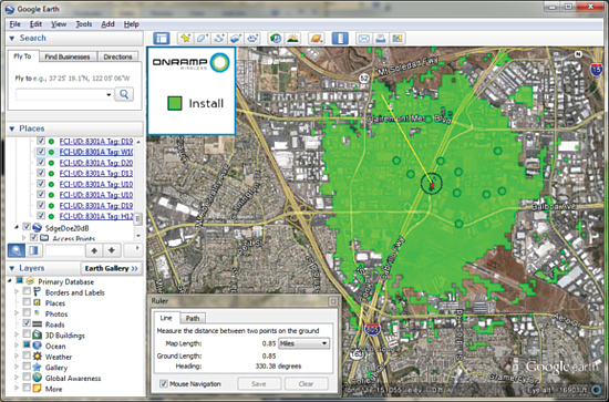
Fig 1: Potential AP site characterized in terms of underground reach
- Access Point Site Selection: Designing a dedicated DOE technical demonstration network required each utility to identify a superset of asset monitoring targets, and then identify potential Access Point (AP) sites for covering those assets. Based on ease of site acquisition and installation, and opportunity to select a range of valuable/viable end point locations, candidate AP locations were chosen. By identifying all utility assets in the surrounding area of a site, and then testing the actual coverage from the AP site to each type of asset location, the candidate site locations were then narrowed down. Due to the larger area and unique design of each underground vault, it was noted that the relationship of predicted to actual coverage measurements for underground vaults was more variable than for other installation locations. Final AP sites were chosen based on predicted ability to provide reliable communications for the maximum number of target assets.
- Network Installation: Both utilities elected pilot grade installations versus permanent commercial grade installations; hence, the APs were installed using free standing mounts, existing power, and existing backhaul services. Install time per AP was approximately 3 to 4 hours, which included full site verification upon installation. The field network was configured to be managed by the On-Ramp Wireless hosted back office solution, and the end-to-end network connectivity and performance verified. Combined, the SDG&E and SCE networks included:
- Hosted access to the On-Ramp Wireless Total View network management, security, and infrastructure monitoring application suite.
- 8 On-Ramp Wireless APs, the only field installed infrastructure, with each AP covering underground assets up to 1 mile away from an AP.
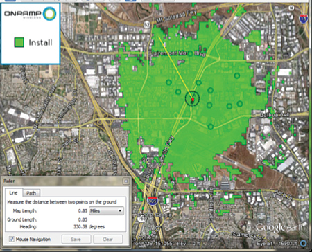
Fig 2: Non-penetrating On-Ramp Wireless Access installation
- Endpoint Installation: Once the APs were sited, each utility selected various endpoints to reflect all variables faced in underground monitoring:
- Locations for both Schweitzer Engineering Laboratories FCI monitors and GridSense TIQ transformer monitors were identified to demonstrate monitoring multiple endpoints on a single communications network. The locations spanned different types of enclosures:
- 3 Manholes
- 5 Underground Vaults
- 16 Handholes
- 44 Padmounts
- Configuration of both the line-powered TIQs and the battery powered FCI monitors brought each utility an opportunity to better understand tailoring of reporting requirements to endpoint capabilities.
- Selection of all hard-to-reach installation locations gave the utilities with planning data for all installation requirements in their territory.
- Locations for both Schweitzer Engineering Laboratories FCI monitors and GridSense TIQ transformer monitors were identified to demonstrate monitoring multiple endpoints on a single communications network. The locations spanned different types of enclosures:
As expected, the teams encountered installation challenges such as water in manholes and various critters inhabiting enclosures, but all endpoints were installed in a matter of weeks. The endpoints installed in padmounts took approximately 1 to 2 hours each, and those in vaults, handholes or manholes took approximately 3 to 4 hours each due to added traffic control and utility safety requirements for accessing the below ground locations. In addition to mounting the actual FCI or TIQ monitoring device, the corresponding antenna configuration was optimized for best fit for the location of the monitored endpoint and coverage characteristics of the enclosure.
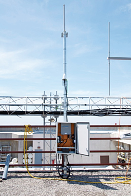
Fig 3: Antenna diversity shown for a manhole endpoint installation
Once finished, the endpoints reported both status and alarm information:
- 30 Schweitzer Engineering Laboratories Underground 8301D Radio Rangers and 8301A Wireless Analog Interface Units reported underground FCI data every 6 to 24 hours and sent alarms based on configurable operating thresholds such as fault detection, current measurement, load statistics across twelve inputs (typically 4 circuits by 3 ways).
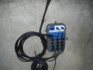
Fig 4: SEL Underground 8301A Faulted Circuit Indicator
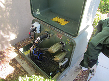
Fig 5: GridSence TIQ Smart Transformer Monitor
- Data Gathering and Analysis: The On-Ramp Wireless project team monitored network and endpoint performance and generated weekly reports of data link quality throughout the 6 month period of the demonstration. Results were summarized in various DOE Deliverables provided throughout the project duration.
DOE Study Results
The project team successfully completed the DOE study, signifying a commercial wireless communications solution can be deployed by any utility working to address reliability of their underground grid:
- The wireless communications reliability of 99.8 percent of data packets received far surpassed other wireless communications technologies deployed underground asset monitoring.
- Network planning methodologies adapted for the challenges of covering static and hard-to-reach assets, such as those installed underground, proved highly accurate when validated against actual field measurements
- The Schweitzer Engineering Laboratories and GridSense devices provided data that helped SDG&E and SCE predict reductions of underground line outage durations by an average of 90 minutes for a commercial deployment, lining them up to achieve the DOE 2015 and 2016 SAIDI reduction targets of 5 percent and 10 percent respectively
- The On-Ramp Total Reach Network proved it could provide reliable monitoring coverage for underground assets located in vaults, manholes, hand holes, pad mounts, and other hard-to-reach locations cost effectively.
The Benefits of Monitoring Underground Assets
The benefits of automating below ground distribution grids is understood, and the On-Ramp Total Reach Network and partner monitoring solutions demonstrated an automation solution that fully positions utilities to meet DOE 2020 outage reduction goals. Additionally, the benefits of the solution extend beyond reduced outage time with additional information about power quality, load, voltage and other parameters. It showed that the On-Ramp Wireless solution enables utility companies to operate and manage electric distribution grids more efficiently, reduce energy use, pinpoint outage locations more quickly, and increase worker safety.
Currently, both utilities are actively evaluating additional monitoring opportunities like water level in underground vaults with the On- Ramp Total Reach Network. The rich data collected during the project contributed to the generation of the first network planning model designed specifically for statically deployed assets, applicable to designing both above ground and below ground monitoring solutions. Ultimately, the DOE-funded study achieved its objectives with the demonstration of a cost-effective commercial solution for monitoring underground grid assets.
All partners involved in the study are actively expanding the networks used for the demonstration, and working with other utility partners to evaluate use of the solution in their networks.
Additional References
The DOE project deliverables referenced for this discussion provide more detail about the study methodology, execution, and results:
- Smart Grid Automation for Underground Utility Assets, Wireless System Trade Study; prepared for U.S. Department of Energy, Office of Electricity Delivery and Energy Reliability, Smart Grid Research and Development; DOE-FOA-313; Contract DE-OE0000550; available now.
- DOE Program Final Report, Wireless System Analysis; prepared for U.S. Department of Energy, Office of Electricity Delivery and Energy Reliability, Smart Grid Research and Development; DOE-FOA-313; Contract DE-OE0000550; available April 2013.
About the Author
 Jason Wilson comes to On-Ramp Wireless with years of experience in product and program management in the telecommunications, defense electronics, and wireless industries. He earned a MS in Systems Management from the University of Southern California, and a BS in Astronautical Engineering from the United States Air Force Academy. Prior to joining On-Ramp Wireless, Jason was VP of Product Management at Ostendo Technologies, where he executed the development of an innovative immersive, curved screen display and secured a major DOD contract win for advanced imaging technologies. Before his time at Ostendo, Jason served in various product and program management roles at large companies and start-ups including L-3 Communications, TollBridge Technologies, and Nortel Networks. Early in his career, Jason served as an officer in the United States Air Force as a program manager for what are now the Delta IV and Atlas V launch vehicle systems.